logo

Détails des produits

Created with Pixso. À la maison Created with Pixso. Produits Created with Pixso.
Contrôleur ESP
Created with Pixso.

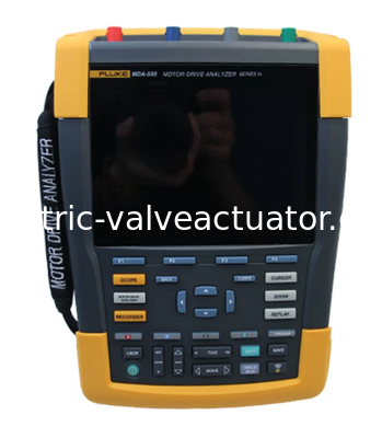
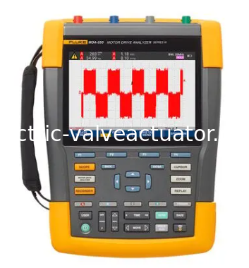
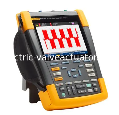
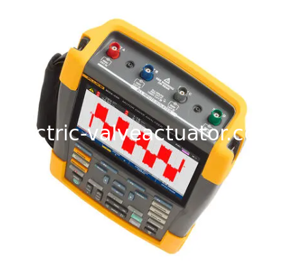
Fluke MDA-550 Series III Motor Drive Analyzer for Variable Frequency Drive Testing

Fluke MDA-550 Series III Motor Drive Analyzer for Variable Frequency Drive Testing

Nom De Marque: Fluke
Numéro De Modèle: Série MDA-550
Quantité De Produit: 1
Prix: Negotistical
Informations détaillées
Lieu d'origine:
OEM
Détails d'emballage:
Nouvelle boîte d'origine
Description du produit
Measurement and Analysis Combination
 
Test Point Subgroup Reading 1 Reading 2 Reading 3 Reading 4
 
Motor Driver Input
 
Voltage and Current
 
Phase - Phase V-A-Hz V ac+dc A ac+dc Hz
 
V peak V peak max V peak min V pk-to-pk Peak Coefficient
 
A peak A peak max A peak min A pk-to-pk Peak Coefficient
 
Phase - Ground V-A-Hz V ac+dc A ac+dc Hz
 
V peak V peak max V peak min V pk-to-pk Peak Coefficient
 
A peak A peak max A peak min A pk-to-pk Peak Coefficient
 
Voltage Imbalance Imbalance V ac+dc V ac+dc V ac+dc Imbalance
 
Peak V pk-to-pk V pk-to-pk V pk-to-pk
 
Current Imbalance Imbalance A ac+dc A ac+dc A ac+dc Imbalance
 
 Fluke MDA-550 Series III Motor Drive Analyzer for Variable Frequency Drive Testing
Peak A pk-to-pk A pk-to-pk A pk-to-pk
 
Motor Driver DC Bus
 
DC V dc V pk-to-pk V peak max
 
Ripple V ac V pk-to-pk Hz
 
Motor Driver Output
 
Voltage and Current (Filtered) V-A-Hz V PWM A ac+dc Hz V/Hz
 
V peak V peak max V peak min V pk-to-pk Peak Factor
 
A peak A peak max A peak min A pk-to-pk Peak Factor
 
Voltage Imbalance Imbalance V PWM V PWM V PWM Imbalance
 
Peak V pk-to-pk V pk-to-pk V pk-to-pk
 
Current Imbalance Imbalance A ac+dc A ac+dc A ac+dc Imbalance
 
Peak A pk-to-pk A pk-to-pk A pk-to-pk Voltage Modulation
 
Phase-Phase Scaling 1 V PWM V pk-to-pk Hz V/Hz
 
Scaling 2 V peak max V peak min Voltage Increment
 
Peak Scaling 3 V peak max Voltage Increment/sec Peak Rise Time Overshoot
 
Scaling 3 Levels Voltage Increment Voltage Increment/sec Rise Time Level Overshoot
 
Phase-Ground Scaling 1 V PWM V pk-to-pk V peak max V peak min
 
Scaling 2 V Peak max V peak min Voltage Increment Hz
 
Peak Scaling 3 V Peak max Voltage Increment/sec Peak Rise Time Overshoot
 
Scaling 3 Levels Voltage Increment Voltage Increment/sec Rise Time Level Overshoot
 
Phase-DC + Scaling 1 V PWM V pk-to-pk V Peak max V peak min
 
Scaling 2 V peak max V peak min Voltage Increment Hz
 
Peak Scaling 3 V peak max Voltage Increment/sec Peak Rise Time Overshoot
 
Scaling 3 Levels Voltage Increment Voltage Increment/sec Rise Time Level Overshoot
 
Phase-DC - Scaling 1 V PWM V pk-to-pk V peak max V peak min
 
Scaling 2 V peak max V peak min Voltage Increment Hz
 
Peak Scaling 3 V peak max Voltage Increment/sec Peak Rise Time Overshoot
 
Scaling 3 Levels Voltage Increment Voltage Increment/sec Rise Time Level Overshoot
 
Motor Input
Voltage and Current (Filtered) V-A-Hz V PWM A ac+dc Hz V/Hz
 
V peak V peak max V peak min V pk-to-pk Peak Factor
 
A peak A peak max A peak min A pk-to-pk Peak Factor
 
Voltage Imbalance Imbalance V PWM V PWM V PWM Imbalance
 
Peak V pk-to-pk V pk-to-pk V pk-to-pk
 
Current Imbalance Imbalance A ac+dc A ac+dc A ac+dc Imbalance
 
Peak A pk-to-pk A pk-to-pk A pk-to-pk
 
Voltage Modulation
 
Phase - Phase Scaling 1 V PWM V pk-to-pk Hz V/Hz
 
Scaling 2 V peak max V peak min Voltage Increment
 
Peak Scaling 3 V peak max Voltage Increment/sec Peak Rise Time Overshoot
 
Scaling 3 Levels Voltage Increment Voltage Increment/sec Rise Time Level Overshoot
 
Phase - Ground Scaling 1 V PWM V pk-to-pk V peak max V peak min
 
Scaling 2 V peak max V peak min Voltage Increment Hz
 
Peak Scaling 3 V peak max Voltage Increment/sec Peak Rise Time Overshoot
 
Scaling 3 Levels Voltage Increment Voltage Increment/sec Rise Time Level Overshoot
 
Motor Shaft
 
Shaft Voltage Event Off V pk-to-pk
 
Event On Voltage Increment Rise/Fall Time Voltage Increment/sec Event/sec
 
Motor Driver Inputs, Outputs, and Motor Inputs
 
Harmonics Voltage V ac V fundamental Hz fundamental % THD
Current A ac A fundamental Hz fundamental THD/TDD Percentage
Measurement Function Specifications
DC Voltage (V dc)
Maximum Voltage, 10:1 or 100:1 Probe 1000 V
Maximum Resolution (Ground Voltage) with 10:1 or 100:1 Probe 1mV/10mV
Full Scale Reading 999 Counts
Accuracy from 4 s to 10 us/div ± (1.5% + 6 counts)
True RMS Voltage (V ac or V ac + dc) (when DC Coupling Function Selected)
Maximum Voltage (Ground Voltage) with 10:1 or 100:1 Probe 1000 V
Maximum Resolution (Ground Voltage) with 10:1 or 100:1 Probe 1 mV/10 mV
Full Scale Reading 999 Counts
DC to 60 Hz ± (1.5% + 10 mV) (Counts)
 
60 Hz to 20 kHz ± (2.5% + 15 counts)
 
20 kHz to 1 MHz ± (5% + 20 counts)
 
1 MHz to 25 MHz ± (10% + 20 counts)
 
Pulse Width Modulation Voltage (Vpwm)
 
Applications: Measuring pulse width modulated signals, such as motor driver inverter output signals.
 
Principle: The reading displays the effective voltage obtained based on the average of the sampled values ​​over the entire cycle of the fundamental frequency.
 
Accuracy: Same as Vac+dc for sinusoidal signals.
 
Peak Voltage (Vpeak)
 
Modes: Maximum peak, minimum peak, or interpeak
 
Maximum voltage (ground voltage) using a 10:1 or 100:1 probe: 1000 V
 
Maximum resolution using a 10:1 or 100:1 probe: 10 mV
 
Accuracy: Maximum peak, minimum peak ± 0.2 div
Interpeak ± 0.4 div
Full-scale reading: 800 Count
 
Current (AMP), using current clamp
 
Range Same as Vac, Vac+dc, or Vpeak
 
Scale Factor 0.1 mV/A, 1 mV/A, 10 mV/A, 20 mV/A, 50 mV/A, 100 mV/A, 200 mV/A, 400 mV/A
 
Accuracy Same as Vac, Vac+dc, or Vpeak (with current clamp accuracy)
 
Frequency (Hz)
Range 1.000 Hz to 500 MHz
Full Scale Reading 9999 counts
 
Accuracy ±(0.5% + 2 counts)
 
Voltage/Frequency Ratio (V/Hz)
 
Application Displays the V PWM value (see V PWM) measured on an AC motor speed drive divided by the fundamental frequency.
 
Accuracy % Vrms + % Hz
Voltage Imbalance Driver Input
 
Application Displays a phase voltage divided by 3 The highest percentage difference of the average of three true RMS voltages
Accuracy: Indicative percentage based on Vac+dc values
Voltage imbalance driver output and motor input
Application: Displays the highest percentage difference of a phase voltage divided by the average of three pulse width modulation voltages
Accuracy: Indicative percentage based on V PWM values
Current imbalance driver input
Application: Displays the highest percentage difference of a phase current divided by the average of three AC current values
Accuracy: Indicative percentage based on Aac+dc values
Current imbalance driver output and motor input
Application: Displays the highest percentage difference of a phase current divided by the average of three AC current values
Accuracy: Indicative percentage based on A ac values
Rise time and fall time
Readings: Voltage difference (dV), time difference (dt), voltage difference divided by time difference (dV/dT), overshoot
Accuracy: Same as oscilloscope accuracy
Harmonics and spectrum
Harmonics: DC to 51st order
Spectral range: 1…9 kHz, 9-150 kHz (20 MHz filter on), up to 500 MHz (Voltage Modulation)
Axis Voltage
Events/Sec
Indicative percentage based on rise and fall time (pulse discharge) measurement
Report Data Acquisition
Number of Screens
Typical 50 screens can be saved in the report (depending on compression ratio)
Transfer to Computer
Use a 2 GB USB flash drive (32 GB or less) or a mini-USB to USB cable or WiFi connectivity with FlukeView™ 2 for ScopeMeter®
Probe Settings
Voltage Probes: 1:1, 10:1, 100:1, 1000:1, 20:1, 200:1
Current Clamp: 0.1 mV/A, 1 mV/A, 10 mV/A, 20 mV/A, 50 mV/A, 100 mV/A, 200 mV/A, 400 mV/A
Axis Voltage Probes: 1:1, 10:1, 100:1
Safety
General Information: IEC 61010-1: Pollution Degree 2
Measurement: Measurement Standard: IEC 61010-2-030: CAT IV 600 V/CAT III 1000 V
Maximum voltage between any terminal and ground: 1000 V
Maximum input voltage via VPS410-II or VPS421: 1000 V CAT III/600 V CAT IV
BNC input A, B, C, D directly: 300 V CAT IV
Maximum floating voltage, using a test tool or a test tool with VPS410-II/VPS421 voltage probes: 1000 V CAT III/600 V CAT IV from any terminal to ground; 1000 V CAT III/600 V CAT IV between any terminals
Operating voltage between probe tip and probe reference lead: VPS410-II: 1000 V
VPS421: 2000 V