logo

Détails des produits

Created with Pixso. À la maison Created with Pixso. Produits Created with Pixso.
Contrôleur ESP
Created with Pixso.

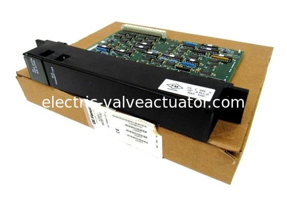
GE FANUC IC697BEM713 , Bus Transmitter Module , 500 Kbytes/Sec

GE FANUC IC697BEM713 , Bus Transmitter Module , 500 Kbytes/Sec

Nom De Marque: GE
Numéro De Modèle: IC697BEM713
Quantité De Produit: 1
Prix: Negotiations
Informations détaillées
Lieu d'origine:
USA
Fente requise:
1
Entrée de tension:
5 volts de C.C
Tirage au courant:
1,4 ampères
Statut LED:
3
Détails d'emballage:
Nouvelle boîte originale
Mettre en évidence:

GE FANUC IC697BEM713 bus transmitter module

,

ESP controller module with 500 Kbytes/Sec

,

GE FANUC bus transmitter with warranty

Description du produit
GE FANUC IC697BEM713, Bus Transmitter Module, 500 Kbytes/Sec
Product Description
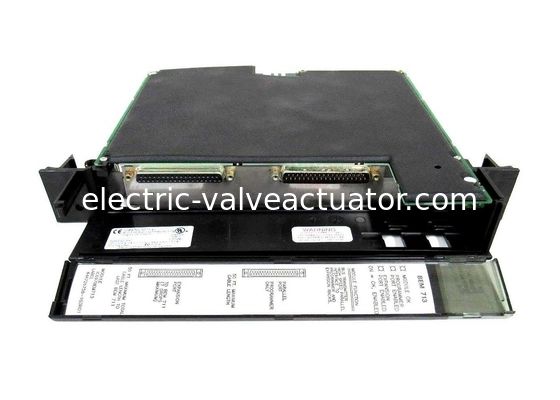
The IC697BEM713 is a Bus Transmitter Module (BTM) from the series 90-70 manufactured by GE Fanuc. The IC697BEM713 module allows expansion from the main CPU rack when the system requires additional modules (up to seven added IC697 PLC racks). The high performance parallel programming function is an important feature. Additionally, this BTM is easy to configure and does not require the use of DIP switches.
The IC697BEM713 module resides in a single slot and has two connectors:
  • A top connector for attaching to the programming device
  • A bottom connector for daisy-chained arrangement via BRMs to expansion racks
The bus transmitter module should be configured using the MS-DOS or Windows programming software configuration function.
Status Indicators
Three status LEDs alert the user to issues with the port and/or module:
  • MODULE OK LED (Top): Shows ON when CPU software completes BTM configuration and has polled each system expansion rack. OFF indicates these conditions are not met.
  • Programmer Port Enabled LED (Middle): Blinks or shows ON when programmer and PLC are communicating. OFF when not communicating.
  • Expansion Port Enabled LED (Bottom): Blinks ON when BTM is communicating with Bus Receiver Modules. OFF if not communicating.
Installation Notes
  • Have the appropriate programmer controller manual for reference
  • Power must be OFF before installation
  • Module cannot be installed in slot 1
  • Must be installed to the right of any IC697 interrupt source modules
Technical Specifications
Feature Specification
Series Series 90-70
Expansion Capacity Up to 7 additional IC697 PLC racks
Power Requirements 5V DC, 1.4A
Data Rate (Both Interfaces) 500 Kbytes/Sec
Maximum Cable Length 50 feet
Slot Requirements Single slot (cannot be installed in slot 1)
Note: The rack power should be turned off prior to module installation and can be turned on after the module is installed in the rack.